![]() Thu Dec 06, 2012 10:53 pm
Thu Dec 06, 2012 10:53 pm
Helpfull blueprints for automation creators
Lubrication system and spark plugs
I'll be posting some blueprints every once in a while, these blueprints can be useful for the game and anyone else that might like to know something about engineering. I will try my best to explain every blueprint I upload so that anyone can understand better.

First blueprint I posted is of the lubrication system and a spark plug. Most don't know this, but the engine oil also cools down the engine besides lubricating it.
From the picture we can observe the basic components of the lubricating system, this is a basic one for your understanding, the system can have much more components depending on the auxiliary systems and pieces bolted to the engine, like turbos, intercooler, and any other parts that needs lubrication.
Blueprint waypoints:
1- Oil filter, cleans the oil of debris and any other contaminants.
2- Oil temperature "sensor", reads the temperature of the oil, the quotes are there because sensor is not a correct term for any measuring apparatus, the correct term is transmitter
3- Hydraulic cam follower, using oil pressure from the system it keeps the valve lift the same through the varying engine temperatures, because metal expands and contracts with temperatures, and to keep up with this phenomenon you have to vary the distance between the cam follower and the camshaft
4- Oil nozzle, it sprays the bottom of the piston to keep the overall temperature of it as low as possible, it also sprays the bottom part of the cylinder with oil for lubrication
5- Oil sump, it's sort of an oil reservoir, but also sediments the heavier oil debris on the bottom of it
6- Oil collector, as it's name says, it collects the oil from the sump, but also has a sift to stop bigger particles from getting in the engine, it's not set at the bottom of the sump, it has 1-2 centimeters of lift so that it doesn't aspirate the muck that gathered itself on the bottom of it
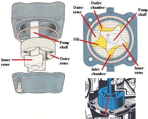
7- Oil pump, it's connected to the engine by the timing belt.
The blueprint of the spark plug is very simple, 1 and 2 are the 2 electrodes between which the sparks are formed.
If I have made some grammar errors, keep in mind English is not my first language.
Here is a picture to drool on
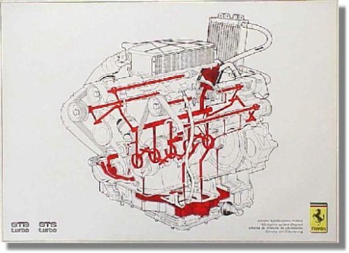
A lubrication system from a Ferrari engine.
Also the spark plug can come in different forms, with more electrodes:
2

3

4

As far as I know 4 is the maximum number. These could give you a substantial power increase, but only if the engine is power oriented, economical engines would have a too small power increase to be felt, but it would still improve the quality of the ignition.
Engine layouts and camshaft positions
Types of engine layouts, camshaft position variations and timing belts, chains and sprockets.

The two A engine layouts are OHV ( over head valve) and it refers to an older type of engine in which the camshaft is positioned lower in the engine, this was most in use with carburetor, because with the camshaft in this type of engine also powered the fuel pump, as seen in the picture below:

In the first picture 1 and 2 is the push rod that pushes the rocker arm which will press on the valve stem. In the second picture the same system but with a hydraulic push rod.
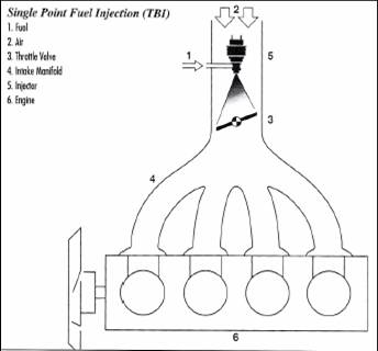
The c engine is OHC (over head camshaft), also an old engine type used mostly for the first generations of injection, the single point injection (SPI) and multiple port injection (MPI). It's main characteristic is that the camshaft is positioned over the valves.
SPI injection:
MPI injection:

it has an injector for every cylinder, but the injection is made in front of the admission valve
The b engine is the widely used DOHC (double over head camshaft), it's used in most of the modern engines because it can have upward of 3 valves per cylinder, making the admission and exhaust to happen in a much shorter period of time and with better efficiency.
The first picture in the bottom half of the image is the timing sprocket variant of the distribution, it was used a lot 30-40 years ago, but it was discontinued due to making too much noise, it's the best type of distribution because it never needed replacement. It was mostly in use with the OHV engine type and carburetor, OHC and DOHC have a bigger distance between camshaft and crankshaft for this type of distribution.
The second one is the distribution chain or timing chain, it's still in use in high end cars and some Corean and Japanese manufacturers, it generally doesn't need replacing although there are some manufacturers that recommend it being changed every 200.000 km. It's considered too be too costly by most European based car companies, but in reality they rather you change you distribution belt every couple of thousand miles just to get more money from you.
The third one is the timing belt, it's made from rubber with a cloth inlay to strengthen it up, it's the widely used solution, it's cheap and in the long run it makes more money for the car companies, the only differences between it and the timing chain is the short replacement time and the fact that you can't push the car when having engine problems because it will skip a tooth and mess up the distribution timing. If the distribution timing is off you valves will hit the piston and both of them will be needing replacement.
I'll be posting some blueprints every once in a while, these blueprints can be useful for the game and anyone else that might like to know something about engineering. I will try my best to explain every blueprint I upload so that anyone can understand better.
First blueprint I posted is of the lubrication system and a spark plug. Most don't know this, but the engine oil also cools down the engine besides lubricating it.
From the picture we can observe the basic components of the lubricating system, this is a basic one for your understanding, the system can have much more components depending on the auxiliary systems and pieces bolted to the engine, like turbos, intercooler, and any other parts that needs lubrication.
Blueprint waypoints:
1- Oil filter, cleans the oil of debris and any other contaminants.
2- Oil temperature "sensor", reads the temperature of the oil, the quotes are there because sensor is not a correct term for any measuring apparatus, the correct term is transmitter
3- Hydraulic cam follower, using oil pressure from the system it keeps the valve lift the same through the varying engine temperatures, because metal expands and contracts with temperatures, and to keep up with this phenomenon you have to vary the distance between the cam follower and the camshaft
4- Oil nozzle, it sprays the bottom of the piston to keep the overall temperature of it as low as possible, it also sprays the bottom part of the cylinder with oil for lubrication
5- Oil sump, it's sort of an oil reservoir, but also sediments the heavier oil debris on the bottom of it
6- Oil collector, as it's name says, it collects the oil from the sump, but also has a sift to stop bigger particles from getting in the engine, it's not set at the bottom of the sump, it has 1-2 centimeters of lift so that it doesn't aspirate the muck that gathered itself on the bottom of it
7- Oil pump, it's connected to the engine by the timing belt.
The blueprint of the spark plug is very simple, 1 and 2 are the 2 electrodes between which the sparks are formed.
If I have made some grammar errors, keep in mind English is not my first language.
Here is a picture to drool on
A lubrication system from a Ferrari engine.
Also the spark plug can come in different forms, with more electrodes:
2
3
4
As far as I know 4 is the maximum number. These could give you a substantial power increase, but only if the engine is power oriented, economical engines would have a too small power increase to be felt, but it would still improve the quality of the ignition.
Engine layouts and camshaft positions
Types of engine layouts, camshaft position variations and timing belts, chains and sprockets.
The two A engine layouts are OHV ( over head valve) and it refers to an older type of engine in which the camshaft is positioned lower in the engine, this was most in use with carburetor, because with the camshaft in this type of engine also powered the fuel pump, as seen in the picture below:
In the first picture 1 and 2 is the push rod that pushes the rocker arm which will press on the valve stem. In the second picture the same system but with a hydraulic push rod.
The c engine is OHC (over head camshaft), also an old engine type used mostly for the first generations of injection, the single point injection (SPI) and multiple port injection (MPI). It's main characteristic is that the camshaft is positioned over the valves.
SPI injection:
MPI injection:
it has an injector for every cylinder, but the injection is made in front of the admission valve
The b engine is the widely used DOHC (double over head camshaft), it's used in most of the modern engines because it can have upward of 3 valves per cylinder, making the admission and exhaust to happen in a much shorter period of time and with better efficiency.
The first picture in the bottom half of the image is the timing sprocket variant of the distribution, it was used a lot 30-40 years ago, but it was discontinued due to making too much noise, it's the best type of distribution because it never needed replacement. It was mostly in use with the OHV engine type and carburetor, OHC and DOHC have a bigger distance between camshaft and crankshaft for this type of distribution.
The second one is the distribution chain or timing chain, it's still in use in high end cars and some Corean and Japanese manufacturers, it generally doesn't need replacing although there are some manufacturers that recommend it being changed every 200.000 km. It's considered too be too costly by most European based car companies, but in reality they rather you change you distribution belt every couple of thousand miles just to get more money from you.
The third one is the timing belt, it's made from rubber with a cloth inlay to strengthen it up, it's the widely used solution, it's cheap and in the long run it makes more money for the car companies, the only differences between it and the timing chain is the short replacement time and the fact that you can't push the car when having engine problems because it will skip a tooth and mess up the distribution timing. If the distribution timing is off you valves will hit the piston and both of them will be needing replacement.
Last edited by Ridicol on Tue Dec 11, 2012 6:15 pm, edited 1 time in total.